|
Aircraft
and Human Performance |
Aircraft Systems
|
| Basic
Aerodynamics |
Communication Procedures |
Enroute Flight |
|
Flight Instruments
|
Navigation |
Procedures and Airport Operations |
| Regulations | Weather | Weather Services | First Aid & Physiology |
Flight Instruments
Table of Contents
Pitot-Static InstrumentsAirspeeds and the Airspeed Indicator
The Altimeter and Altitudes
Gyroscopic Instruments
Attitude Indicator
Turn Coordinator
Heading Indicator
Magnetic Compass (Northern Hemisphere)
Pitot-Static Instruments
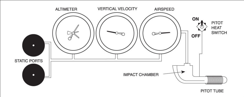
The pressure altimeter, vertical speed indicator, and airspeed indicator operate in response to pressures through the pitot-static system. See Figure 3-1.
Static (atmospheric) pressure is taken from the static vents and is provided to all three instruments. Clogging of the static vents or line will cause all three instruments to become inoperative or to display erroneous readings.
Impact (ram) pressure is taken from the pitot tube and furnished to the airspeed indicator only. Clogging of the pitot opening will not affect operation of the altimeter or vertical speed indicator.
Airspeeds and the Airspeed Indicator
A pilot must be familiar with the following airspeed terms and abbreviations:
Indicated airspeed (IAS)—the uncorrected reading obtained from the airspeed indicator.
Calibrated airspeed (CAS)—indicated airspeed corrected for installation and instrument error.
True airspeed (TAS)—calibrated airspeed corrected for temperature and pressure variations.
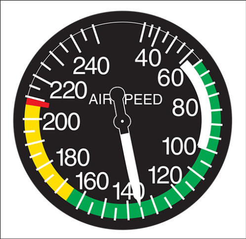
A number of airspeed limitations, known as V-speeds, are indicated by color-coded marking on the airspeed indicator (see Figure 3-2):
VS0—stall speed or minimum steady flight speed in the landing configuration (the lower limit of the white arc).
VFE—maximum flap extended speed (the upper limit of the white arc). The entire white arc defines the flap operating range.
VS1—the stall speed or minimum steady flight speed in a specified configuration (the lower limit of the green arc). The entire green arc defines the normal operating range.
VNO—the maximum structural cruising speed (the upper limit of the green arc and lower limit of the yellow arc). The yellow arc defines the caution range, which should be avoided unless in smooth air.
VNE—never-exceed speed (the upper limit of the yellow arc) marked in red.
There are other important airspeed limitations that are not color-coded on the airspeed indicator:
VLE—the maximum landing gear extended speed.
VA—the design maneuvering speed. If rough air or severe turbulence is encountered, airspeed should be reduced to maneuvering speed or less to minimize stress on the airplane structure.
VY—the best rate-of-climb speed (the airspeed that will result in the most altitude in a given period of time).
VX—the best angle-of-climb speed (the airspeed that will result in the most altitude in a given distance).
The Altimeter and Altitudes
An altimeter is an instrument used to measure height (altitude) by responding to atmospheric pressure changes. See Figure 3-3.
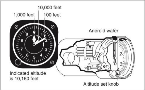
Altitude is indicated by three hands on the face of the altimeter. The shortest hand indicates altitude in tens of thousands of feet; the intermediate hand, in thousands of feet; and the longest hand in hundreds of feet. The altimeter is subdivided into 20-foot increments.
Altitude means elevation with respect to any assumed reference level, and different terms identify the reference level used. See Figure 3-4.
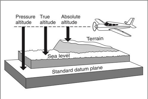
Indicated altitude—the altitude read on the altimeter after it is set to the current local altimeter setting.
Absolute altitude—the height above the surface.
True altitude—the true height above mean sea level (MSL) normally measured in feet.
Pressure altitude—the altitude that is indicated whenever the altimeter setting dial (Kohlsman window) is adjusted to 29.92. This is the standard datum plane; a theoretical level where air pressure is equal to 29.92 inches of mercury ("Hg). The standard datum plane may be above, at, or below sea level.
Density altitude—the pressure altitude corrected for nonstandard temperature and/or pressure. Rotating the setting knob on the altimeter simultaneously rotates the setting dial and the altimeter hands at a rate of one inch per 1,000 feet of altitude. Thus, increasing the setting dial from 29.15 to 29.85 would cause the hands of the altimeter to show an increase of 700 feet.
Prior to takeoff, the altimeter should be set to the current local altimeter setting. This is the value to which the scale of the altimeter is set so that the altimeter indicates true altitude at field elevation. If the altimeter setting is not available, the altimeter should be set to the elevation of the departure airport.
After takeoff, the altimeter should remain set to the current local altimeter setting until climbing through 18,000 feet MSL. At that time, the altimeter should be set to 29.92.
On a standard day (29.92 "Hg and +15°C) at sea level, pressure altitude, true altitude, indicated altitude, and density altitude are all equal. Any variation from standard temperature or pressure will have an effect on the altimeter.
To compensate for the effect of nonstandard conditions, the altimeter must be set to the altimeter setting of a station within 100 NM of the aircraft (unless it is above 18,000 feet MSL).
If a flight is made from an area of low pressure/low temperature to an area of high pressure/high temperature without adjusting the altimeter setting, the altimeter will indicate lower than the actual altitude above ground level. If a flight is made from an area of high pressure/high temperature to an area of low pressure/low temperature without adjusting the altimeter setting, the altimeter will indicate higher than the actual altitude above mean sea level.
.JPG)
Gyroscopic Instruments
Some aircraft instruments use gyroscopes. Simply stated, gyroscopes are rapidly spinning wheels or disks which resist any attempt to move them from their plane of rotation. This is called “rigidity in space.” Three aircraft instruments which use gyroscopes are the attitude indicator, the turn coordinator, and the heading indicator.
Attitude Indicator
.JPG)
The rigidity in space principle makes the gyroscope an excellent artificial horizon around which the attitude indicator (and the airplane) pivot.
When viewing the attitude indicator, the direction of bank is determined by the relationship of the miniature airplane to the horizon bar. The miniature airplane may be moved up or down from the horizon with an adjustment knob. Normally, the miniature airplane will be adjusted so that the wings overlap the horizon bar whenever the airplane is in straight-and-level flight.
Turn Coordinator
The turn coordinator uses a miniature airplane to provide information concerning rate of roll and rate of turn. As the airplane enters a turn, movement of the miniature aircraft indicates rate of roll. When the bank is held constant, rate of turn is indicated. Simultaneously, the quality of turn, or movement about the yaw axis, is indicated by the ball of the inclinometer.
Heading Indicator
The heading indicator is designed to avoid many of the errors inherent in a magnetic compass. However, the heading indicator does suffer from precession, caused mainly by bearing friction. Because of this precessional error, the heading indicator must periodically be realigned with the magnetic compass during straight-and-level, unaccelerated flight.
Magnetic Compass (Northern Hemisphere)
Deviation is a compass error caused by magnetic disturbances from electrical and metal components in the aircraft. The correction for this error is displayed on a compass correction card placed near the magnetic compass in the aircraft. Variation is the angular difference between the true, or geographic, poles and the magnetic poles at a given point. The compass magnet is aligned with the magnetic poles, while aeronautical charts are oriented to the geographic poles. This variation must be taken into consideration when determining an aircraft’s actual geographic location. Indicated on charts by isogonic lines, it is not affected by the airplane’s heading.
The magnetic compass, attracted to a magnetic field in the earth, points down as well as north. This downward pointing tendency, called magnetic dip, causes errors in compass indications.
When turning toward north from an easterly or westerly heading, the compass lags behind the actual aircraft heading. When a turn is initiated while on a northerly heading, the compass first indicates a turn in the opposite direction. The compass lags whenever turns are made to or from north.
When turning toward south from an easterly or westerly heading, the compass leads the actual aircraft heading. When a turn is initiated while on a southerly heading, the compass shows an immediate lead in the same direction as the turn. The compass leads whenever turns are made to or from south.
Accelerating or decelerating while heading either east or west will also cause compass errors. If acceleration occurs on a heading of east or west, the compass will indicate a turn to the north, while deceleration will cause an indication of a turn to the south. Therefore, it becomes apparent that the indications of a magnetic compass are accurate only during straight-and-level, unaccelerated flight.
The magnetic compass is also influenced by lines of force from magnetic fields within the aircraft. These errors are called deviations.
Some common mnemonics to help you remember compass errors in the northern hemisphere are UNOS (Undershoot North, Overshoot South) for turns and ANDS (Accelerate North, Decelerate South) for changes in velocity.