|
Aircraft
and Human Performance |
Aircraft Systems
|
| Basic
Aerodynamics |
Communication Procedures |
Enroute Flight |
|
Flight Instruments
|
Navigation |
Procedures and Airport Operations |
| Regulations | Weather | Weather Services | First Aid & Physiology |
Basic Aerodynamics
Table of Contents
Aerodynamic TermsAxes of Rotation and the Four Forces Acting in Flight
Lift
Weight
Thrust
Drag
Stability
Turns, Loads, and Load Factors
Maneuvers
Rectangular Course
Turns Around a Point
S-Turns
Stalls and Spins
Flaps
Ground Effect
Wake Turbulence
Aerodynamic Terms
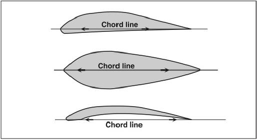
An airfoil is a structure or body which produces a useful reaction to air movement. Airplane wings, helicopter rotor blades, and propellers are airfoils. See Figure 1-1.

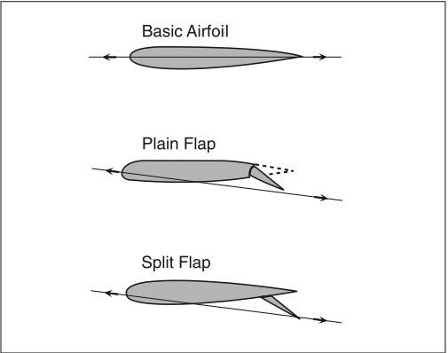
The chord line is an imaginary straight line from the leading edge to the trailing edge of an airfoil. See Figure 1-2. Changing the shape of an airfoil (by lowering flaps, for example) will change the chord line. See Figure 1-3.
In aerodynamics, relative wind is the wind felt by an airfoil. It is created by the movement of air past an airfoil, by the motion of an airfoil through the air, or by a combination of the two. Relative wind is parallel to and travels in the opposite direction of the flight path of the airfoil.
The angle of attack is the angle between the chord line of the airfoil and the relative wind. By manipulating the aircraft controls, the pilot can vary the angle of attack.
The angle of incidence is the angle at which a wing is attached to the aircraft fuselage. The airplane pilot has no control over the angle of incidence.
Axes of Rotation and the Four Forces Acting in Flight
Aircraft have three axes of rotation: the lateral axis, longitudinal axis, and the vertical axis. See Figure 1‑7.
The lateral axis is an imaginary line from wing tip to wing tip for an airplane. The rotation around this axis is called pitch. Pitch is controlled by the elevators, and this rotation is referred to as longitudinal control or longitudinal stability. See Figure 1-8.
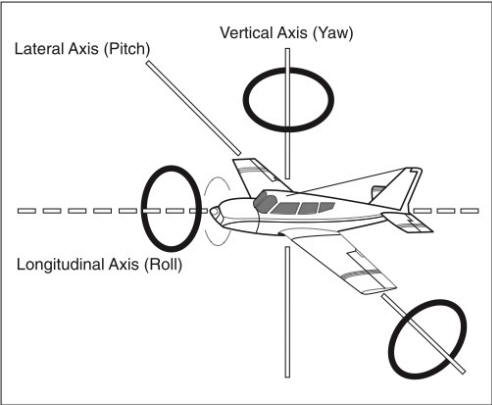
The longitudinal axis is an imaginary line from the nose to the tail. Rotation around the longitudinal axis is called roll. Roll is controlled by the ailerons, and this rotation is referred to as lateral control or lateral stability. See The vertical axis is an imaginary line extending vertically through the intersection of the lateral and longitudinal axes. Rotation about the vertical axis is called yaw. Yaw is controlled by the rudder, and this rotation is referred to as directional control or directional stability.
The center of gravity (CG) (the imaginary point where all the weight is concentrated) is the point at which an airplane would balance if it were suspended at that point. The three axes intersect at the center of gravity. Weight-shift control and powered parachutes rotate around this center of gravity.
Four aerodynamic forces are considered to be basic because they act upon an aircraft during all flight maneuvers: there is the downward-acting force called weight which must be overcome by the upward-acting force called lift; and there is the rearward-acting force called drag, which must be overcome by the forward-acting force called thrust.
Lift
Air is a gas which can be compressed or expanded. When compressed, more air can occupy a given volume and air density is increased. When allowed to expand, air occupies a greater space and density is decreased. Temperature, atmospheric pressure, and humidity all affect air density. Air density has significant effects on an aircraft’s performance.
As the velocity of a fluid (gas or liquid) increases, its pressure decreases. This is known as Bernoulli’s principle.
Lift is the result of a pressure difference between the top and the bottom of the wing. A wing is designed to accelerate air over the top camber of the wing, thereby decreasing the pressure on the top and producing lift. See
Several factors are involved in the creation of lift: angle of attack, wing area and shape (planform), air velocity, and air density. All of these factors have an effect on the amount of lift produced at any given moment. The pilot can actively control the angle of attack and the airspeed, and increasing either of these will result in an increase in lift.
Weight
Weight is the force with which gravity attracts all bodies vertically toward the center of the earth.
Thrust
Thrust is the forward force which is produced by the propeller acting as an airfoil to displace a large mass of air to the rear.
Drag
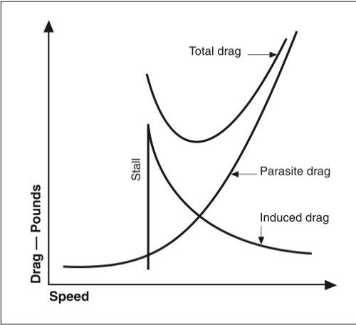
Drag is a rearward-acting force which resists the forward movement of an airplane through the air. Drag may be classified into two main types: parasite drag and induced drag.
Parasite drag is the resistance of the air produced by any part of an airplane that does not produce lift (antennae, landing gear, etc.). Parasite drag will increase as airspeed increases.
Induced drag is a by-product of lift. In other words, drag is induced as the wing develops lift. The high-pressure air beneath the wing, which is trying to flow around and over the wing tips into the area of low pressure, causes a vortex behind the wing tip. This vortex induces a spanwise flow and creates vortices all along the trailing edge of the wing. As the angle of attack is increased (up to the critical angle), lift will increase and so will the vortices and downwash. This downwash redirects the lift vector rearward, causing a rearward component of lift (induced drag). Induced drag will increase as airspeed decreases. See Figure 1-14.
During unaccelerated (straight-and-level) flight, the four aerodynamic forces which act on an airplane are said to be in equilibrium, or:
Lift = Weight and Thrust = Drag
Stability
Stability is the inherent ability of an airplane to return, or not return, to its original flight condition after being disturbed by an outside force, such as rough air.
Positive static stability is the initial tendency of an aircraft to return or not return to its original position. .
Positive dynamic stability is the tendency of an oscillating airplane (with positive static stability) to return to its original position relative to time.
Aircraft design normally ensures that the aircraft will be stable in pitch. The pilot can adversely affect this longitudinal stability by allowing the CG to move forward or aft of specified CG limits through improper loading procedures. One undesirable flight characteristic a pilot might experience in an airplane loaded with the CG located aft of the aft CG limit would be the inability to recover from a stalled condition.
The location of the CG with respect to the center of lift (CL) will determine the longitudinal stability of an airplane.
An airplane will be less stable at all airspeeds if it is loaded to the most aft CG. An advantage of an airplane said to be inherently stable is that it will require less effort to control.
Changes in pitch can also be experienced with changes in power settings (except in T-tail airplanes). When power is reduced, there is a corresponding reduction in downwash on the tail, which results in the nose “pitching” down.
A properly designed weight-shift control is stable because the center of lift is above the CG. Slower than trim, the center of lift moves aft. Faster than trim, the center of lift moves forward to make the aircraft stable.
Turns, Loads, and Load Factors
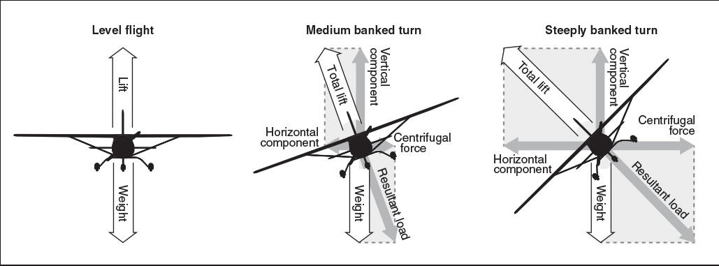
When an airplane is banked into a turn, a portion of the vertical lift being developed is diverted into a horizontal lift component. It is this horizontal (sideward) force that forces the airplane from straight-and-level flight and causes it to turn. The reduced vertical lift component results in a loss of altitude unless total lift is increased by increasing angle of attack, increasing airspeed, or increasing both. See Figure 1-18.
In aerodynamics, load is the force (imposed stress) that must be supported by an airplane structure in flight. The loads imposed on the wings in flight are stated in terms of load factor.
In straight-and-level flight, the wings of an airplane support a load equal to the sum of the weight of the airplane plus its contents. This particular load factor is equal to “One G,” where “G” refers to the pull of gravity.
However, a force called centrifugal force is generated which acts toward the outside of the curve any time an airplane is flying a curved path (turns, climbs, or descents).
Whenever the airplane is flying in a curved flight path with a positive load, the load that the wings must support will be equal to the weight of the airplane plus the load imposed by centrifugal force; therefore, it can be said that turns increase the load factor on an airplane.
As the angle of bank of a turn increases, the load factor increases.
The amount of excess load that can be imposed on the wing of an airplane depends on the speed of the airplane. An example of this would be a change in direction made at high speed with forceful control movement, which results in a high load factor being imposed.
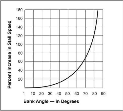
An increased load factor (weight) will cause an airplane to stall at a higher airspeed, as shown in Figure 1-20.
Some conditions that increase the weight (load) of an aircraft are: overloading the airplane, too steep an angle of bank, turbulence and abrupt movement of the controls.
Because different types of operations require different maneuvers (and therefore varying bank angles and load factors), aircraft are separated into categories determined by the loads that their wing structures can support:
The limit loads should not be exceeded in actual operation, even though a safety factor of 50% above limit loads is incorporated in the strength of the airplane.
ASTM consensus standards determine similar load limits for light-sport aircraft.
Maneuvers
Rectangular Course
For best results when planning a rectangular course, the flight path should be positioned outside the field boundaries just far enough that they may be easily observed from either pilot seat by looking out the side of the airplane. The closer the track of the airplane is to the field boundaries, the steeper the bank necessary at the turning points.
Turns Around a Point
When flying turns around a point, the wings will be in alignment with the pylon only during the time the airplane is flying directly upwind or directly downwind. At all other points, a wind correction angle will keep the wings from pointing directly at the pylon.
If the student is instructed to not exceed a 45° bank in a turn around a point maneuver, the best place to start is the point where the bank angle will be steepest, which is when flying downwind. Throughout the remainder of the maneuver, the bank will be shallowing out.
The ground speed will be equal where the airplane is flying with the same headwind component. The angle of bank will be the same only where the airplane is flying directly crosswind.
S-Turns
In a steep turn, the ground speed will be the same when the airplane has the same headwind component. The steepest angle of bank is required at the points where the airplane is flying downwind. The airplane will have to be crabbed into the wind the greatest amount where it is flying crosswind.
In the first half of an S-turn, the bank should begin shallow and increase in steepness as the airplane turns crosswind, and become steepest where the turn is downwind. If the turn is started with too steep a bank angle, the bank will increase too rapidly and the upwind half of the “S” will be smaller than the downwind half. The turn will not be completed by the time the airplane is over the reference line.
Stalls and Spins
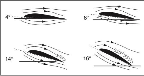
As the angle of attack is increased (to increase lift), the air will no longer flow smoothly over the upper wing surface but instead will become turbulent or “burble” near the trailing edge. A further increase in the angle of attack will cause the turbulent area to expand forward. At an angle of attack of approximately 18° to 20° (for most wings), turbulence over the upper wing surface decreases lift so drastically that flight can not be sustained and the wing stalls. See Figure 1-24.
The angle at which a stall occurs is called the critical angle of attack. An airplane can stall at any airspeed or any attitude, but will always stall at the same critical angle of attack. The indicated airspeed at which a given airplane will stall in a particular configuration, however, will remain the same regardless of altitude. Because air density decreases with an increase in altitude, the airplane has to be flown faster at higher altitudes to cause the same pressure difference between pitot impact pressure and static pressure.
An aircraft will spin only after it has stalled, and will continue to spin as long as the outside wing continues to provide more lift than the inside wing and the aircraft remains stalled.
Flaps
Extending the flaps increases the wing camber and the angle of attack of a wing. This increases wing lift and also increases induced drag.
The increased drag enables the pilot to make steeper approaches to a landing, without an increase in airspeed. VFR approaches to a landing at night should be made the same as during the daytime.
Ground Effect
Ground effect occurs when flying within one wingspan or less above the surface. The airflow around the wing and wing tips is modified and the resulting pattern reduces the downwash and the induced drag. These changes can result in an aircraft becoming airborne before reaching recommended takeoff speed or floating during an approach to land.
An airplane leaving ground effect after takeoff will require an increase in angle of attack to maintain the same lift coefficient, which in turn will cause an increase in induced drag and, therefore, require increased thrust.
Wake Turbulence
All aircraft leave two types of wake turbulence: prop or jet blast, and wing-tip vortices.
The prop or jet blast could be hazardous to light aircraft on the ground behind large aircraft which are either taxiing or running-up their engines. In the air, jet or prop blast dissipates rapidly.
Wing-tip vortices are a by-product of lift. When a wing is flown at a positive angle of attack, a pressure differential is created between the upper and lower wing surfaces, and the pressure above the wing will be lower than the pressure below the wing. In attempting to equalize the pressure, air moves outward, upward, and around the wing tip, setting up a vortex which trails behind each wing.
The strength of a vortex is governed by the weight, speed, and the shape of the wing of the generating aircraft. Maximum vortex strength occurs when the generating aircraft is heavy, clean, and slow.
Vortices generated by large aircraft in flight tend to sink below the flight path of the generating aircraft. A pilot should fly at or above the larger aircraft’s flight path in order to avoid the wake turbulence created by the wing-tip vortices.
Close to the ground, vortices tend to move laterally. A crosswind will tend to hold the upwind vortex over the landing runway, while a tailwind may move the vortices of a preceding aircraft forward into the touchdown zone.
To avoid wake turbulence when landing, a pilot should note the point where a preceding large aircraft touched down and then land past that point.
On takeoff, lift off should be accomplished prior to reaching the rotation point of a preceding large aircraft; the flight path should then remain upwind and above the preceding aircraft’s flight path.