Lear 35 Annunciator
(FC530)
Click on an indication to learn what it does

 One or both
current limiters failed. Check Voltmeter Battery Voltage=Both CL's Failed. Index
One or both
current limiters failed. Check Voltmeter Battery Voltage=Both CL's Failed. Index
 Fuel below 400 -
500 pounds in either tank. Index
Fuel below 400 -
500 pounds in either tank. Index
 Less than .25 psi
fuel pressure to engine. Light extinguishes at 1 psi.
Less than .25 psi
fuel pressure to engine. Light extinguishes at 1 psi.
Memory items: Thrust Lever Retard, Standby Pump On, Air Ignition On.
A low fuel pressure switch is located between the fuel shutoff valve and the engine-driven fuel pump in
each engine feed line.The light extinguishes when pressure increases above 1.0 psi.
Illumination of a FUEL PRESS warning light is an indication of loss of fuel pressure to the
engine. The probable cause is failure of the affected wing jet pump. The engine-driven pump is
capable of suction-feeding enough fuel to sustain engine operation without either the wing standby
pump or jet pump. However, 25,000 feet is the highest altitude at which continuous operation should
be attempted in this event. Index
 or
or  (FC530) Steady- Spoilers not locked down. Flashing-Spoilers
deployed with 13 degrees
(FC530) Steady- Spoilers not locked down. Flashing-Spoilers
deployed with 13 degrees
or more flaps extended. Index
 Electric door hook
not fully retracted, or one of 10 latch pins not fully engaged. Index
Electric door hook
not fully retracted, or one of 10 latch pins not fully engaged. Index
 Either: 1-
Spoilers split 6 degrees or more, or 2- Spoiler and aileron split 6 degrees or
more
Either: 1-
Spoilers split 6 degrees or more, or 2- Spoiler and aileron split 6 degrees or
more
in spoileron mode. Index
 or
or  Either: 1- One or both Pitot Heaters is inoperative with the switches on,
or 2- One or both Pitot Heat switches is off. Index

A fuel filter is installed in each engine feed line to filter the fuel before it enters the engine-driven
fuel pump. Should the filters become clogged, the fuel is allowed to bypass them. A differential pressure
switch installed in each filter assembly illuminates the one amber FUEL FILTER annunciator light if either
or both filters are bypassing fuel (Annunciator Panel section).
Index
 Either: 1- Switch
is off and valve is open, or 2- Switch is on with insufficient pressure, or
Either: 1- Switch
is off and valve is open, or 2- Switch is on with insufficient pressure, or
failure of valves to open. Index
 Either: 1- Switch
is off, or 2- Computer has failed with the switch on. Index
Either: 1- Switch
is off, or 2- Computer has failed with the switch on. Index
 Steady: System is
off or failed. (During pusher actuation it is normal)
Steady: System is
off or failed. (During pusher actuation it is normal)
Flashing: In shaker range. Index
 Vertical gyro has
failed. Index
Vertical gyro has
failed. Index
 System inoperative
above .69 Mach with autopilot off. Overspeed warning sounds above .74 Mach. Index
System inoperative
above .69 Mach with autopilot off. Overspeed warning sounds above .74 Mach. Index
 L or right NAC
Heat switches are on. Index
L or right NAC
Heat switches are on. Index
 Inverter is
off line. Index
Inverter is
off line. Index
 Inverter is
off line. Index
Inverter is
off line. Index
 Inverter has
failed with the switch on. Index
Inverter has
failed with the switch on. Index
 Oil pressure in
one or both engines is below 23 psi. Index
Oil pressure in
one or both engines is below 23 psi. Index
 Stabilizer
structure is too hot. Index
Stabilizer
structure is too hot. Index
 Windshield heat
has been shut off by a temperature limit. Index
Windshield heat
has been shut off by a temperature limit. Index
 Nosewheel Steering
is engaged. Index
Nosewheel Steering
is engaged. Index
 Pylon or Duct
temperature too hot. Both lights on: Manifold overpressure (some SN's.) Index
Pylon or Duct
temperature too hot. Both lights on: Manifold overpressure (some SN's.) Index
 Generator is off
line. Index
Generator is off
line. Index
 (SN
> 113) Cabin altitude has
reached 8750 feet and controller has switched to manual mode. (SN >113)
Index
(SN
> 113) Cabin altitude has
reached 8750 feet and controller has switched to manual mode. (SN >113)
Index
At 9,500 the Emergency Pressurization Valves are activated,
directing engine bleed air directly into the cabin.
At 10,100 the cabin altitude warning horn sounds.
At 11,500 the cabin altitude limiters actuate.
At 14,000 the passenger oxygen masks deploy and cabin overhead lights
illuminate.
Diff Press for relief of the outflow valve is 8.9. Diff Press relief for the
safety valve is 9.2.
(SN < 113) At 10,000 the controller has switched to manual mode. Index
At 11,500 the cabin altitude limiters actuate.
At 14,000 the passenger oxygen masks deploy and cabin overhead lights
illuminate.
Diff Press for relief of the outflow valve is 8.9. Diff Press relief for the
safety valve is 9.2.
Cabin Alt 10,000’ Warning Memory Items
(Emergency Descent)
1. Crew Oxygen Masks DON & Select 100%
2. Thrust levers IDLE
3. Autopilot DISENGAGE
4. Spoilers EXTEND
5. Landing Gear (below Mmo or Vle) DOWN
6. Descend at Mmo/Vle but not below MSA
7. PASS OXY Valve NORMAL
8. PASS MASK Valve MAN
 Wing Structure
temperature too hot. Index
Wing Structure
temperature too hot. Index
 Windshield
anti-ice valve is open. Index
Windshield
anti-ice valve is open. Index
 Alcohol tank is
empty. (Early: System pressure is low.) Index
Alcohol tank is
empty. (Early: System pressure is low.) Index
 One or both
battery temps are as indicated or higher. Index
One or both
battery temps are as indicated or higher. Index
 Engine sync switch
is on with nose gear down and locked. Index
Engine sync switch
is on with nose gear down and locked. Index
 Aircraft is on the
ground and horizontal stabilizer is not trimmed for takeoff. Index
Aircraft is on the
ground and horizontal stabilizer is not trimmed for takeoff. Index
 Wheel Master
Switch is depressed, Primary pitch trim has a fault (potential runaway) or
Wheel Master
Switch is depressed, Primary pitch trim has a fault (potential runaway) or
Primary pitch trim is running at fast speed with flaps up. Index
 Illuminates
whenever a Red Annunciator Illuminates. Index
Illuminates
whenever a Red Annunciator Illuminates. Index
 Ferrous metal
particles have been detected in the engine oil. Index
Ferrous metal
particles have been detected in the engine oil. Index
 System Pressure
1,125 pounds or less. Index
System Pressure
1,125 pounds or less. Index
 A green or amber FUEL XFLO annunciator light (Annunciator Panel section)
on the glareshield illuminates continuously whenever the crossflow valve is fully open.
If wing fuel imbalance occurs, as in single-engine operation, crossflow is accomplished by opening the
crossflow valve and turning on the standby pump in the heavy wing, while
ensuring that the opposite
standby pump is off. The transfer rate is approximately 50 pounds of fuel per minute.
With both engines operating, opening the crossflow valve to balance fuel should not be attempted when a
red FUEL PRESS light is illuminated unless it can be accomplished below 25,000 feet. To do so would divert
pressure from the affected engine-driven pump to the crossflow line. Instead, asymmetric power settings
may be used to balance fuel, if necessary. The above considerations do not apply to single-engine
operations, and normal cross-flow operations may be performed as usual. Index
 Indicated
engine oil pressure is low. Index
Indicated
engine oil pressure is low. Index
 Fire or
overheat is detected in the associated engine. Handle shuts off Fuel,
Fire or
overheat is detected in the associated engine. Handle shuts off Fuel,
Bleed Air, Hydraulic, and arms both bottles. Index
Memory Items:
1. Thrust Lever IDLE UNLESS CRITICAL THRUST SITUATION
2. If fire continues more than 15 seconds or there are other indications of
fire:
a. Thrust Lever CUTOFF
b. Engine Fire Pull Handle PULL
c. ARMED Light DEPRESS ONE
 Fire
Extinguisher System is Armed. Depressing an illuminated ARMED Light
Fire
Extinguisher System is Armed. Depressing an illuminated ARMED Light
Discharges the contents of one fire extinguisher bottle into the affected engine
nacelle. Index
 Illumination of any red anti skid lights indicates a malfunction.
For anti-skid to work, Switch must be on, Both squat switches must be in the
ground mode,
Parking brake must be released, and Taxi speed must be greater than 10 Kts. Index
 Illumination
of both Red Main Gear Unsafe Light indicates
Illumination
of both Red Main Gear Unsafe Light indicates
Main Gear Inboard Doors are not fully closed. After Manual gear extension, both
L & R Unsafe lights
remain illuminated. Index
|
Fuel
Panel
|
Illumination of Fuel Jettison Lights indicate the
respective jettison valve is opened. Index
Crossflow Valve opens or closes whenever transfer-fill
switch or fuselage valve switch is moved. with power applied. Index
Except for FUEL JETSN, all other amber lights, when
illuminated steady indicate the respective valve position disagrees with
the switch position
With only Fuselage Valve Open 162 pounds remains in
Fuselage Tank.Index
|
|
Fuel System Shown Without Gravity Flow Line
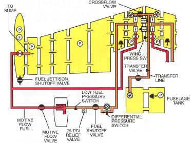
|
see also With Gravity Flow
Without Gravity Flow Line Index
Valve sequence FILL
(Xfer/Fill Switch to FILL):
1- Transfer Valve Opens,
2- Crossflow Valve Opens,
3- Standby Pumps Energize.
4- Float Switch Enabled.
See green full light below.
Valve sequence OFF
(Xfer/Fill Switch OFF):
1- Transfer Valve Closes,
2- Crossflow Valve Closes,
3- Standby Pumps OFF.
4- Float Switch Disabled.
Valve sequence XFER
(Xfer/Fill Switch XFER):
1- Transfer
Valve Opens,
2- Crossflow Valve Opens,
3- Transfer Pump Energizes.
4- Standby Pumps Disabled.
5- Pressure Switch Enabled.
Valve sequence OFF
(Xfer/Fill Switch OFF):
1- Transfer Pump Shuts Off.
2- Standby Pumps Enabled.
3- Transfer Valve Closes,
4- Crossflow Valve Closes.
5- Press. Switch Disabled. Index
|
|
Fuel System With Gravity Flow Line
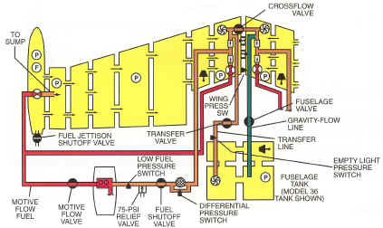
|
With Gravity Flow Line Index
Valve sequence FILL
(Xfer/Fill Switch to FILL):
1- Transfer
& Fuselage Valves Open,
2- Crossflow Valve Opens,
3- Standby Pumps
Engage.
4- Float Switch Enabled.
See green full light below.
Valve sequence OFF
(Xfer/Fill Switch OFF):
1- Transfer &
Fuselage Valves Close,
2- Crossflow Valve Closes,
3- Standby Pumps OFF. Index
Valve sequence XFER
(Xfer/Fill Switch XFER):
1- Transfer
Valve Opens,
2- Crossflow Valve Opens,
3- Transfer Pump Energizes.
4- Standby Pumps Disabled.
5- Pressure Switch Enabled.
Valve sequence OFF
(Xfer/Fill Switch OFF):
1- Transfer Pump Shuts Off.
2- Standby Pumps Enabled.
3- Transfer Valve Closes,
4- Crossflow Valve Closes.
5- Press. Switch Disabled. IIndex
|
Fuselage Valve Switch
When the FUS VALVE switch is
positioned to OPEN, both the fuselage valve and the crossflow valves
simultaneously open. When fuel is transferred in this manner, 162 pounds
of fuel remain in the fuselage
tank. Gravity Transfer is possible on al airplanes through the normal transfer
line. An alternate method of
transferring fuel in flight is possible on aircraft equipped with the FUS Valve
Switch by opening it.
Prior to doing so, it is essential to first assure that the XFER-FILL switch is OFF
and that both standby
pump switches are off. Then when the FUS Valve Switch is placed in
the OPEN Position, the fuselage
valve and crossflow valve open simultaneously. The valves are not sequenced as
they are when using the
XFER-FILL switch. Index
Standby Pump
When either Standby Pump is on, the
FUS VALVE switch is rendered inoperative, and neither the fuselage
valve nor the crossflow valve will open if the fuselage moved to OPEN.
If the FUS VALVE switch is already in the OPEN position, (FUS VALVE and
CROSSFLOW VALVE OPEN)
turning either Standby Pump Switch on will automatically cause the fuselage
valve and the crossflow valves
to sequence closed. Index
GREEN
FULL LIGHT
When filling the fuselage tank, a float switch shuts off the standby pump,
closes the Transfer and Crossflow
valves, then closes the Fuselage Valve (if so equipped). The float switch then
illuminates the green FULL light.
The green FULL light remains illuminated until the XFER-FILL switch is turned
off. Index
White EMPTY Light
With the XFER Switch in the XFER position, the White
EMPTY light illuminates when the fuselage tank low pressure
switch closes. This light will illuminate when either of 2 conditions exist:
1- The Fusulage Tank is Empty.
2- The Fuselage Transfer Pump has failed.
The Wing Fuel Pressure Switch prevents overpresurization of the wings during
fuel transfer. The switch
deenergizes the fuselage transfer pump when wing pressure reaches 5 psi; the
switch resets when the
pressure drops below 2.5 psi. Index
Jet Pump Switches
There are 4 jet pumps - one in each wing and one in each tip tank. The
switches control electric motive-flow valves.
The amber light next to the switches indicates the motive flow valves are in
transit, or not in the position selected by
the switch. Each switch controls both jet pumps on that side. Index
Amber Light Adjacent to the Fuel CROSS
FLOW Switch
The amber light adjacent to the CROSS FLOW switch illuminates when the valve is in transit or
is not in the position selected. If wing fuel imbalance occurs, as in single-engine operation,
crossflow is accomplished by opening the crossflow valve and turning on the standby pump
in the heavy wing, while en-suring that the opposite standby pump is off.
The transfer rate is approximately 50 pounds of fuel per minute.
With both engines operating, opening the crossflow valve to balance fuel should not be attempted when a
red FUEL PRESS light is illuminated unless it can be accomplished below 25,000 feet. To do so would divert
pressure from the affected engine-driven pump to the crossflow line. Instead, asymmetric power settings
may be used to balance fuel, if necessary. The above considerations do not apply to single-engine
operations, and normal cross-flow operations may be performed as usual. Index
Amber Light Adjacent to the Fuel XFER-FILL
Switch
The amber light adjacent to the XFER-FILL switch illuminates when the valve is in transit or is not
in the position selected. The valve is powered through the right main bus FILL & XFER circuit breaker.
Index
Amber light adjacent to the FUS VALVE
switch.
The amber light adjacent to the FUS VALVE switch will illuminate when the fuselage valve is in transit or is not in the position selected.
As an option of SNs 35-299 through 35-596, and as standard equipment on 35-597 and subsequent, and on all 36 models, a DC motor-driven fuselage valve is installed in a
second fuel line, connecting the fuselage tank with the crossflow manifold on the right side of the crossflow valve.
The valve is controlled by the FUS VALVE switch on the fuel control panel. When the FUS VALVE switch is positioned to OPEN, both the fuselage valve and the crossflow valve simultaneously open, allowing fuel to gravity-flow from the fuselage tank to both wings. When fuselage fuel is transferred in this manner, 162 pounds of fuel remain in the fuselage tank. The
fuselage valve is also controlled by the XFER-FILL switch. When placed to FILL, the
transfer valve, fuselage valve, and crossflow valve are sequenced open, and the standby pumps are energized to pump wing tank fuel through both fuel lines into the fuselage tank. The fuselage valve remains closed when the XFER-FILL switch is positioned to XFER. The amber light adjacent to the FUS VALVE switch will illuminate when the fuselage valve is in transit or is not in the position selected. If either standby pump switch is on, the FUS VALVE switch is rendered inoperative, and neither the fuselage valve nor the crossflow valve will open if the FUS VALVE switch is moved to OPEN. Conversely, if the FUS VALVE switch is already in the OPEN position (fuselage valve and crossflow valve open), turning either standby pump switch on will automatically cause the fuse-lage valve and crossflow valves to sequence closed. The fuselage valve is powered through the left essential bus FUSE VAL (or FUS VALVE) circuit breaker.
Index
Index

Index
Type Ratings